

What Is Battery Thermal Runaway? Why Can a Single Cell Failure Affect an Entire Energy Storage Container?
BMS monitoring, gas detection, PACK protection, battery cluster isolation, and fire suppression all play important roles in energy storage safety. But why can a single cell failure affect an entire energy storage container? And why are isolation and explosion protection still necessary when fire suppression is already installed? The answer lies in battery thermal runaway.
Thermal runaway is a self-accelerating process in which internal chemical reactions generate excessive heat, potentially causing gas release, fire, and propagation to neighboring cells.
Table of Contents
- How Does Battery Thermal Runaway Occur? Five Common Causes
- Why Can a Single Cell Failure Spread Across an Entire Energy Storage Container?
- Gas Release During Thermal Runaway: Why Pressure Relief Does Not Eliminate the Risk
- Can a BMS Prevent Battery Thermal Runaway?
- Fire Protection in Energy Storage Containers: Why Suppression Alone Is Not Enough
- Explosion Protection and Thermal Isolation: Key Preventive Measures
- How to Evaluate the Safety Design of an Energy Storage System Before Purchasing
- Conclusion: A Multi-Layer Approach to Energy Storage Safety
- Frequently Asked Questions
Under normal operating conditions, the electrochemical reactions within lithium-ion cells remain stable. However, overcharging, short circuits, mechanical damage, and excessive temperatures can disrupt this balance, potentially triggering uncontrolled reactions.
The process generally follows this sequence:
Abnormal heat generation → Temperature rise → Internal material decomposition → Further heat release → Accelerated chemical reactions → Thermal runaway.
Five common factors can contribute to this process:
1.1 Overcharging
When the charging protection system malfunctions, a cell may exceed its specified voltage limit. This can initiate unwanted electrochemical reactions, resulting in excessive heat generation. The BMS monitors individual cell voltages and can issue alarms, limit charging current, or disconnect the charging circuit when abnormal readings are detected.
1.2 External Short Circuit
An external short circuit occurs when the positive and negative terminals are unintentionally connected, creating a low-resistance current path. The resulting high current can cause rapid temperature increases. Protective devices such as fuses and circuit breakers help interrupt excessive fault currents and minimize electrical damage.
1.3 Internal Short Circuit
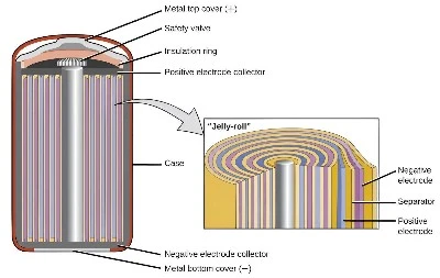
Damage to the separator can bring the positive and negative electrodes into direct contact, creating an internal short circuit. This type of fault is particularly difficult to identify because the initial heat is generated inside the battery rather than on its outer surface. External temperature sensors may not detect such abnormalities in time, meaning that a normal surface temperature does not necessarily rule out internal defects.
During battery manufacturing, charge-discharge testing and aging tests help evaluate voltage, capacity, and charging and discharging performance. The collected data supports production quality control and helps identify electrical abnormalities before cells are assembled into battery packs.
However, these procedures cannot guarantee the identification of every latent internal short circuit.
1.4 Mechanical Damage
Crushing, impact, or penetration can compromise the internal structure of a battery cell, potentially damaging the separator or causing electrode contact. Although the consequences may not be immediately apparent, structural damage can deteriorate during subsequent operating cycles, increasing the possibility of internal short circuits and thermal runaway.
1.5 Excessive Ambient Temperature and Cooling System Failure
Elevated ambient temperatures and malfunctions in liquid or air cooling systems can undermine effective battery thermal management. While neither condition necessarily initiates thermal runaway on its own, both can accelerate temperature buildup, worsen existing faults, and increase the overall safety risk.
Energy storage systems integrate thousands of cells into modules, battery packs, and clusters. Their close arrangement creates pathways for heat transfer between neighboring cells.
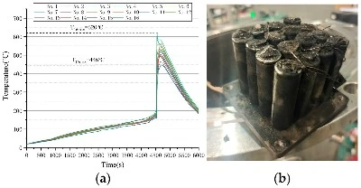
When a cell enters thermal runaway, intense heat and flammable gases may be released. Heat transfer can raise the temperature of adjacent cells, potentially triggering a chain reaction known as thermal runaway propagation.
Passing cell-level safety tests does not guarantee system-level safety.
Laboratory cell testing cannot fully account for risks introduced by PACK and container integration, such as thermal management, electrical isolation, gas accumulation, and fire protection. Without effective insulation, fault isolation, and compartmentalized protection, a localized failure may escalate across the system.
As thermal runaway develops, cell materials decompose and release large volumes of hot, flammable gas. Rising internal pressure activates the cell's safety vent, allowing gas to escape.
However, venting does not eliminate the hazard. Released gases may be toxic and explosive. If they accumulate inside the enclosure, an ignition source can cause a fire or deflagration.
Effective protection requires coordinated gas detection, controlled ventilation, and explosion relief. Exhaust fans alone cannot ensure safety. The design must account for cell chemistry, enclosure layout, and applicable safety standards.
A Battery Management System (BMS) monitors key operating parameters, including cell voltage, current, temperature, state of charge (SOC), state of health (SOH), and insulation resistance. When abnormal conditions arise, it can trigger alarms, restrict power output, or disconnect the charging and discharging circuits.
For battery manufacturers, BMS performance must also be validated during production. Dedicated BMS test equipment evaluates voltage and current measurement, temperature sensing, protection thresholds, cell balancing, and communication interfaces to verify compliance with design specifications.
However, a BMS cannot prevent every thermal runaway event.
Its protective capabilities rely on accurate sensing, reliable signal acquisition, and uninterrupted communication. Internal short circuits can develop rapidly, often before external temperature sensors detect a significant change. Even if the BMS commands a shutdown, it cannot reverse the exothermic reactions already taking place inside a cell.
Therefore, BMS protection is only one layer of battery safety. It must work alongside cell-level safeguards, thermal management, electrical isolation, and fire protection.
Fire protection in energy storage containers typically comprises three coordinated stages: detection (temperature, smoke, and combustible gas monitoring) → alarm and control (fault alerts, charging and discharging shutdown, and isolation of affected battery clusters) → fire suppression (application of suitable extinguishing agents).
Key consideration: Certain extinguishing agents can suppress visible flames but may not stop the exothermic reactions continuing inside battery cells. As a result, the risk of reignition remains.
Fire suppression addresses the consequences of a fault rather than eliminating its underlying cause. A comprehensive safety strategy must also incorporate sustained cooling, thermal propagation control, reignition prevention, and emergency response procedures.
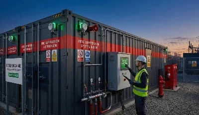
6.1 Cell-Level Thermal Barriers: Insulating materials and PACK structural design help limit heat transfer between adjacent cells, reducing the risk of thermal propagation.
6.2 Battery Cluster Isolation: Electrical segmentation and physical barriers help contain faults within the affected cluster, preventing localized failures from spreading across the entire system.
6.3 Enclosure Gas Management: Gas detection, controlled ventilation, and engineered pressure relief help manage flammable gas accumulation and reduce the risk of explosion.
6.4 Emergency Response Design: Enclosure layouts should accommodate emergency access, personnel evacuation, and firefighting operations.
Common misconception: Explosion protection is not simply a matter of increasing container wall thickness.
Effective explosion protection focuses on controlling flammable gas accumulation, providing appropriately designed pressure relief, and minimizing ignition sources. The design must be supported by engineering assessments based on operating conditions, enclosure configuration, and applicable safety standards-not merely by increasing structural strength.
Do not rely solely on marketing claims such as "multi-layer fire protection." Evaluate the actual engineering measures and supporting test documentation across seven critical areas:
7.1 Cell-Level Safety: Examine the cell chemistry, manufacturing quality controls, and safety test reports relevant to the intended application.
7.2 PACK and System-Level Validation: Verify that safety assessments extend beyond individual cells to include PACK assemblies, battery clusters, and the complete containerized system.
7.3 Thermal Runaway Propagation Mitigation: Identify the design measures used to contain a cell failure and prevent heat transfer from triggering adjacent cells.
7.4 BMS Protection Logic: Review the monitoring and response strategy, including cell-level sensing, fault alarms, power limitation, and protective disconnection.
7.5 Gas Management and Fire Protection: Assess whether gas detection, fire suppression, ventilation, and explosion relief measures are properly matched to the project's risk profile.
7.6 Fault Containment and Isolation: Determine whether a fault in one battery cluster can be contained without compromising the operation or safety of other clusters.
7.7 Operation, Maintenance, and Emergency Preparedness: Check the procedures for routine monitoring, inspection, fault response, fire protection coordination, and on-site emergency management.
Effective energy storage safety begins with preventing faults and limiting their escalation, rather than depending on fire suppression alone after an incident occurs.
Protection must extend across the entire system, from individual cells and PACK assemblies to battery clusters and containerized installations. Cell design provides the foundation for intrinsic safety; PACK integration addresses thermal insulation and electrical protection; cluster-level management enables real-time monitoring and fault isolation; while container and plant-level systems coordinate thermal management, gas detection, fire suppression, and explosion protection.
Capacity and power define a storage system's performance. The integrity of its safety architecture determines its ability to maintain reliable operation throughout its service life.
Q1. Can battery thermal runaway be completely prevented?
Not entirely. However, stringent cell quality control, proper charging management, thermal monitoring, and layered safety measures can reduce the likelihood of thermal runaway and limit its spread.
Q2. Can a BMS detect thermal runaway before it occurs?
A BMS monitors cell voltage, temperature, and current to identify abnormal conditions and initiate protective actions. However, sudden internal faults may escape early detection, making independent gas detection and thermal protection essential.
Q3. Why can batteries reignite after the flames are extinguished?
Extinguishing visible flames does not necessarily stop the internal reactions within affected cells. Residual heat can sustain these reactions, potentially causing reignition or triggering nearby cells.
Q4. Can lithium iron phosphate (LFP) batteries experience thermal runaway?
Yes. Although LFP cells generally offer greater thermal stability than some other lithium-ion chemistries, they remain susceptible to thermal runaway under conditions such as internal short circuits, overcharging, mechanical damage, and excessive temperatures.
Q5. How can thermal runaway propagation be controlled in energy storage containers?
A coordinated protection strategy should include cell quality control, PACK-level thermal barriers, effective cooling, electrical fault isolation, gas detection, ventilation, fire suppression, and explosion protection. These measures help contain localized failures and reduce the risk of system-wide propagation.
Request Battery Cell Testing Equipment For Your Project
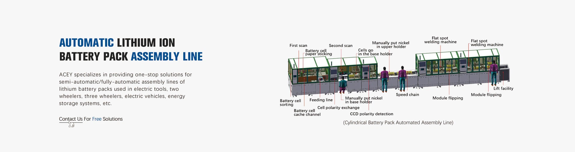
Xiamen Acey New Energy Technology Co., Ltd. supplies equipment for lithium-ion battery research and manufacturing, including battery cell fabrication systems, battery testing equipment, and battery pack assembly machinery.
If your project involves swelling analysis, cell aging, dimensional consistency, or production-quality evaluation, provide the following information to help define the equipment requirements:
Cell format and chemistry
Nominal and maximum voltage
Charge/discharge current range
Required test protocols
Number of test channels
Temperature-control requirements
Dimensional measurement objectives
Laboratory or production application
Contact Acey Intelligent to discuss a suitable equipment configuration for your lithium-ion battery testing and manufacturing project.
Website: https://www.aceyintelligent.com/