

What is the influence of cutting tool geometry on grooving performance?
As a supplier of grooving machines, I've witnessed firsthand the pivotal role that cutting tool geometry plays in determining the overall performance of grooving operations. Grooving is a machining process used to create narrow, precise channels or grooves on a workpiece, and the geometry of the cutting tool can significantly impact the quality, efficiency, and cost - effectiveness of this process.
1. Basics of Cutting Tool Geometry in Grooving
Cutting tool geometry encompasses several key parameters, including rake angle, clearance angle, cutting edge radius, and groove width. Each of these elements has a unique influence on the grooving process.
The rake angle is the angle between the rake face of the cutting tool and the perpendicular to the workpiece surface. A positive rake angle reduces the cutting force required, as it allows the tool to shear the material more easily. This can lead to improved surface finish and reduced power consumption. However, a very large positive rake angle may also weaken the cutting edge, making it more prone to chipping. On the other hand, a negative rake angle provides greater strength to the cutting edge, which is beneficial when machining hard materials, but it increases the cutting force and may result in a rougher surface finish.
The clearance angle is the angle between the flank of the cutting tool and the machined surface of the workpiece. A proper clearance angle prevents the tool from rubbing against the workpiece, reducing friction and heat generation. Insufficient clearance angle can cause excessive wear on the tool flank, leading to poor surface quality and increased cutting forces.
The cutting edge radius is another critical factor. A smaller cutting edge radius allows for a more precise cut and better surface finish, especially when grooving thin - walled or delicate workpieces. But a very small radius may be more susceptible to wear and breakage. A larger cutting edge radius can withstand higher cutting forces, making it suitable for roughing operations or machining hard materials.
The groove width of the cutting tool must match the desired width of the groove on the workpiece. Any deviation can lead to inaccurate groove dimensions, which may render the workpiece unusable.
2. Impact on Surface Finish
One of the most noticeable effects of cutting tool geometry on grooving performance is on the surface finish of the groove. A well - designed cutting tool with appropriate rake and clearance angles, along with a suitable cutting edge radius, can produce a smooth and uniform surface.
For example, a positive rake angle combined with a small cutting edge radius can reduce the amount of material deformation during the cutting process. This results in less tearing and fracturing of the material, leading to a finer surface finish. In contrast, a tool with a large negative rake angle and a large cutting edge radius may cause the material to be pushed and deformed rather than sheared cleanly, resulting in a rough surface with visible tool marks.
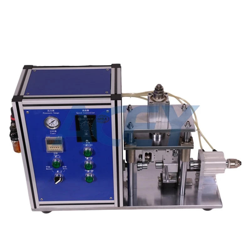
In applications where a high - quality surface finish is required, such as in the production of precision components for the aerospace or medical industries, the selection of the right cutting tool geometry is crucial. Our Cylindrical Battery Grooving Machine is designed to work with a variety of cutting tools, allowing users to optimize the tool geometry for the best surface finish on cylindrical battery casings.
3. Influence on Tool Life
Tool life is a major concern in any machining operation, and cutting tool geometry has a direct impact on it. A tool with improper geometry will experience higher levels of wear and breakage, leading to frequent tool changes and increased production costs.
The rake angle affects the distribution of cutting forces on the tool. An inappropriate rake angle can cause uneven stress distribution, leading to premature wear on certain parts of the cutting edge. For instance, a very large positive rake angle may cause the cutting edge to chip easily, while a large negative rake angle can lead to excessive flank wear.
The clearance angle also plays a role in tool life. Insufficient clearance angle causes the tool to rub against the workpiece, generating heat and increasing friction. This heat can cause the tool material to soften and wear more rapidly. On the other hand, an excessive clearance angle may weaken the tool structure, making it more prone to breakage.
The cutting edge radius is related to the tool's resistance to wear. A larger cutting edge radius can distribute the cutting forces over a larger area, reducing the stress on the edge and increasing the tool's ability to withstand wear. However, as mentioned earlier, a very large radius may not be suitable for all applications.
By optimizing the cutting tool geometry, we can significantly extend the tool life. This means less downtime for tool changes and lower overall production costs. Our grooving machines are engineered to support the use of cutting tools with optimized geometries, ensuring long - lasting performance and reduced tooling expenses for our customers.
4. Effect on Cutting Forces and Power Consumption
Cutting tool geometry has a profound impact on the cutting forces and power consumption during the grooving process. The rake angle is a key determinant of the cutting force. A positive rake angle reduces the cutting force because it allows the tool to penetrate the material more easily. This reduction in cutting force translates into lower power consumption, which is beneficial for both cost - savings and machine longevity.
Conversely, a negative rake angle increases the cutting force, as the tool has to push and shear the material more forcefully. This higher cutting force requires more power from the machine, increasing energy costs and putting more stress on the machine components.
The cutting edge radius also affects the cutting force. A smaller cutting edge radius requires less force to cut through the material, as it can more precisely separate the material. A larger cutting edge radius, while more durable in some cases, may require higher cutting forces due to the increased contact area with the workpiece.
By carefully selecting the cutting tool geometry, manufacturers can optimize the cutting forces and power consumption. This not only reduces operating costs but also improves the overall efficiency of the grooving process. Our grooving machines are designed to work in harmony with well - designed cutting tools, enabling users to achieve optimal cutting force and power consumption levels.
5. Impact on Dimensional Accuracy
Dimensional accuracy is a critical aspect of grooving operations. The cutting tool geometry directly affects the accuracy of the groove dimensions. The groove width of the cutting tool must be precisely controlled to ensure that the resulting groove on the workpiece meets the required specifications.
Any variation in the cutting edge geometry, such as a worn or damaged edge, can lead to inaccurate groove widths. Additionally, the rake and clearance angles can influence the stability of the cutting process. If the angles are not properly set, the tool may deflect during cutting, resulting in non - uniform groove depths and widths.
In applications where tight tolerances are required, such as in the production of electronic components or automotive parts, the selection of the right cutting tool geometry is essential. Our grooving machines are equipped with advanced control systems that can work in conjunction with cutting tools of appropriate geometries to ensure high - precision grooving operations.
6. Considerations for Different Workpiece Materials
Different workpiece materials require different cutting tool geometries for optimal grooving performance. For example, when machining soft materials like aluminum or brass, a tool with a large positive rake angle and a small cutting edge radius is often preferred. This allows for a clean and efficient cut with a good surface finish.

When dealing with hard materials such as stainless steel or titanium, a tool with a negative or small positive rake angle and a larger cutting edge radius is more suitable. These geometries provide the necessary strength to cut through the hard material without excessive wear or breakage.
In the case of composite materials, the cutting tool geometry needs to be carefully selected to avoid delamination or fiber pull - out. A tool with a sharp cutting edge and appropriate rake and clearance angles can ensure a clean cut without damaging the composite structure.
Our grooving machines are versatile and can be used with a wide range of cutting tools, allowing our customers to adapt to different workpiece materials. Whether it's the Cylindrical Battery Grooving Machine for battery casings or other grooving applications, we can provide solutions tailored to the specific material requirements.
Conclusion
In conclusion, cutting tool geometry has a far - reaching influence on grooving performance. It affects the surface finish, tool life, cutting forces, power consumption, dimensional accuracy, and the ability to machine different workpiece materials. As a supplier of grooving machines, we understand the importance of providing our customers with the knowledge and tools to optimize the cutting tool geometry for their specific applications.
If you are looking for a reliable grooving machine solution that can support the use of cutting tools with optimized geometries, we are here to help. Our team of experts can assist you in selecting the right machine and cutting tools for your needs. Contact us to start a discussion about your grooving requirements and explore how our products can enhance your production process.
References
- Kalpakjian, S., & Schmid, S. R. (2008). Manufacturing Engineering and Technology. Pearson Prentice Hall.
- Trent, E. M., & Wright, P. K. (2000). Metal Cutting. Butterworth - Heinemann.
- Shaw, M. C. (2005). Metal Cutting Principles. Oxford University Press.